hen an F5 transmitter starts acting wrong, crews often blame the “antenna” or “coil.” Sometimes that’s true. Often it’s not. The fastest way to waste money is to treat every bad read like an internal failure. The fastest way to lose a bore is to keep running equipment that’s telling you it can’t deliver consistent performance.
This guide gives you a field-first way to decide whether you’re looking at a setup issue, jobsite interference, maintenance problems, or an internal fault that calls for service. It also explains why “coil repair” on a DigiTrak Falcon F5 transmitter (including FT5p and FT5Lp models) isn’t like swapping a wear part. The parts that create the locating signal are internal. Getting to them usually means opening the transmitter—an action that can void warranty coverage under standard warranty terms.
Use this as a checklist. Start with the simple fixes you can do without opening anything. Move to checks that produce clear pass/fail signals. Then decide: keep running, send the unit in for evaluation, or replace it.
What “antenna/coil repair” means on an F5—and why it’s not a field job
On Falcon F5 transmitters, the components tied to signal generation are inside the housing. That’s the key reality behind the “repair vs. replacement” question. If the problem involves internal components, a real repair typically requires opening the transmitter. Standard warranty terms state that modification, opening up, repair, or attempted repair can void warranty coverage. That alone should shape how you approach “coil repair” in the field: don’t turn a service problem into a warranty problem.
There’s also the reliability question. The manufacturer warns that using repaired locating products can introduce significant project risk. The warning is blunt about what can go wrong: workmanship quality varies, some stressed components may not be replaced, and a unit can fail again after a short service life—sometimes “2 or 3 jobs.” That doesn’t mean every repair fails. It means you should treat internal repair as a reliability decision, not just a price decision.
So keep the line clear:
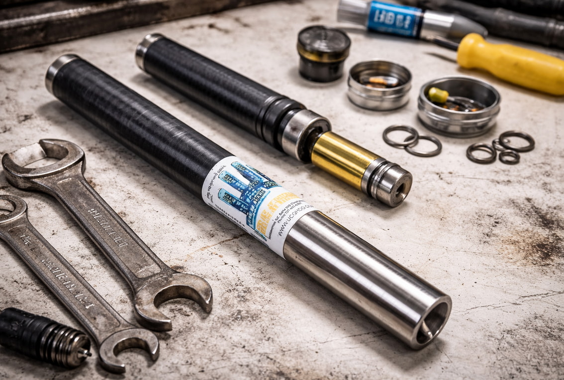
Field-serviceable work is external and non-invasive: cleaning threads and contacts, protecting the fiberglass tube from abrasion, maintaining seals, and confirming correct pairing and operating selections.
Internal repair is specialized service work. If it requires opening the transmitter, it belongs on a bench with proper diagnostics.
Your goal in the field isn’t to rebuild electronics. It’s to rule out the common causes, document the symptoms, and make a clean decision that protects uptime and accuracy.
The symptoms that look like coil trouble—and the ones that don’t
Some problems feel like a “dead coil” because the receiver data looks wrong or unstable. But several common issues can mimic internal failure: pairing mistakes, incorrect transmitter selection on the receiver, poor contact in the battery compartment, or environmental interference. For more information on Falcon F5 transmitter repair, see the site.
Start with what you can control. Confirm the transmitter is powered on and stable. Confirm the receiver is set to the correct transmitter selection and operating mode. If roll and pitch data is missing, treat it as a troubleshooting problem first, not a parts problem. The published troubleshooting guidance for Falcon F5 and F5+ focuses on basics like confirming correct selection, ensuring the transmitter is on, and rerunning optimization or related setup steps.
Next, use repeatability as your filter. If the behavior changes wildly as you move around the site, interference is a strong suspect. If the behavior follows the transmitter from place to place, equipment trouble becomes more likely.
Finally, pay attention to signal behavior at a known distance. The Falcon F5 operator guidance notes that if you check signal strength at 10 feet and later see a change, it can indicate interference—or it can indicate a problem with your equipment. That single sentence is useful because it keeps you honest: you still need to test in a cleaner area before you blame the tool.
The sections below focus on two high-value “decision points” you can use to separate setup and environment from potential internal faults.
Calibration failures and signal-strength extremes: what they tell you
Calibration is one of the clearest checks you can run because it can fail for defined reasons. The Falcon F5 operator guidance documents calibration failure conditions tied to transmitter signal strength: below 300 points (too low) or above 950 points (too high). Those thresholds matter because they turn a vague complaint into a measurable condition.
If you hit a “too low” condition, slow down before you call it internal damage. Low signal can still be the result of basic issues you can fix without opening the transmitter. The general care guidance emphasizes keeping battery cap threads and compartment threads clean, cleaning contact points, and avoiding conditions that promote oxidation or poor electrical contact. A transmitter with poor contact can behave like it’s weak or unstable.
If you hit a “too high” condition, don’t jump to conclusions either. First remove variables: move away from likely interference, confirm you’re operating as intended, and repeat the check. Then look for repeatability. If the same failure shows up again in different locations with the same setup, you have a stronger case that the transmitter needs bench diagnostics rather than more field tinkering.
The practical takeaway is simple: calibration failures at these extremes are not a field “coil replacement” instruction. They’re a stop sign. Once you see consistent failures against published thresholds, you should move from troubleshooting to professional evaluation.
Missing roll/pitch data and pairing problems: rule out setup first
Missing roll and pitch data feels like hardware failure because the readout is incomplete. But published troubleshooting guidance for Falcon F5 systems treats missing data as something you should approach methodically: confirm the transmitter is on, confirm the receiver is set to the correct transmitter selection, and rerun the pairing/optimization steps as needed.
Pairing failures also tend to be simple before they’re serious. The published “cannot pair” guidance focuses on basics: the transmitter must be powered on, and the receiver must be set to the correct transmitter selection to pair.
That’s why the order matters. If you haven’t confirmed selection, power, and pairing, you don’t have enough evidence to suspect an internal coil problem. Many “dead transmitter” reports are really “wrong selection” or “not paired” reports.
Here’s the clean test: if you correct setup and pairing, and the problem still persists across reasonable test conditions—especially if it follows the transmitter across locations—then you’ve earned the right to suspect the equipment. At that point, continuing to chase settings can waste more time than it saves.
Field checks that prevent false “coil failure” calls
Most preventable “transmitter problems” come from neglect, not mystery. General transmitter care guidance puts the emphasis where it belongs: battery compartment health, clean threads, good contact, intact seals, and smart protection from abrasion.
Start with the battery compartment. Keep the spring and contact areas clean. Keep battery cap threads and compartment threads clean. Poor contact can create inconsistent behavior that looks like signal trouble because the transmitter isn’t operating consistently.
Next, protect the seal. The care guidance highlights the O-ring as a maintenance item: keep it in good condition and replace it if it’s damaged. Seal issues matter because they invite contamination and moisture into places you don’t want it. You don’t need a lecture to know how that ends on a jobsite.
Then protect the body and tube without creating new problems. The care guidance supports taping the fiberglass tube for abrasion protection, but it also warns not to cover the IR port. That’s a small detail with a big effect. A “protective” wrap that blocks a port can complicate pairing and communication tasks.
Finally, run your checks in a fair environment. If you’re standing in a hot zone for interference, don’t treat that as a final verdict on the transmitter. Move, repeat, compare. The goal isn’t perfection. It’s a clean test that helps you decide whether you’re dealing with site conditions or equipment.
These steps won’t fix an internal fault. But they will keep you from diagnosing a “coil failure” that was really a maintenance problem.
A “before you blame the coil” checklist you can run in minutes
Use this list when performance drops, calibration fails, or data looks unreliable. It’s built around non-invasive checks and published troubleshooting themes.
Confirm power: Verify the transmitter is powered on and stable.
Clean threads and contacts: Inspect and clean battery cap threads, compartment threads, and contact points. The published care guidance treats clean contact surfaces as routine maintenance, not a special event.
Inspect the O-ring: Check the seal and replace the O-ring if it’s damaged. Don’t treat a compromised seal as “good enough.”
Protect without blocking: If you tape the fiberglass tube for abrasion protection, keep the IR port clear as instructed in the care guidance.
Verify correct selection: On the receiver side, confirm you’ve selected the correct transmitter.
Redo pairing/optimization steps: If you can’t pair or you’re missing roll/pitch data, follow the published troubleshooting logic: power, selection, pairing steps—then retest.
Repeat in a cleaner spot: If results change by location, interference is a suspect. If the behavior follows the transmitter, equipment trouble becomes more likely.
If you’ve run this checklist and the problem persists, stop guessing. That’s when professional evaluation starts saving time and reducing risk.
Repair vs. replacement: how to decide without guessing
Repair vs. replacement isn’t a moral issue. It’s a decision about risk, time, and confidence.
Two manufacturer points should anchor your thinking. First, standard warranty terms state that opening up, modifying, repairing, or attempting repair can void warranty coverage. Second, the manufacturer warns that using repaired locating products can introduce significant project risk, including workmanship variability and the chance that stressed components weren’t replaced—leading to early failure.
So your decision should turn on four practical questions:
Is warranty coverage a factor? If it is, avoid actions that can void coverage. Don’t open the transmitter.
Are your symptoms repeatable against published checks? Calibration failures tied to defined signal-strength extremes, repeated across test conditions, deserve a service decision—fast.
Is the job high-risk? If the cost of uncertainty is high, replacement can be the safer path.
How much downtime can you tolerate? If you can’t afford uncertainty, you need an answer backed by diagnostics, not hope.
Replacement can buy predictability. Repair can be smart when diagnostics show an isolated problem and the unit can be restored to reliable performance. The mistake is guessing. Your field work should narrow the options until the right move becomes obvious.
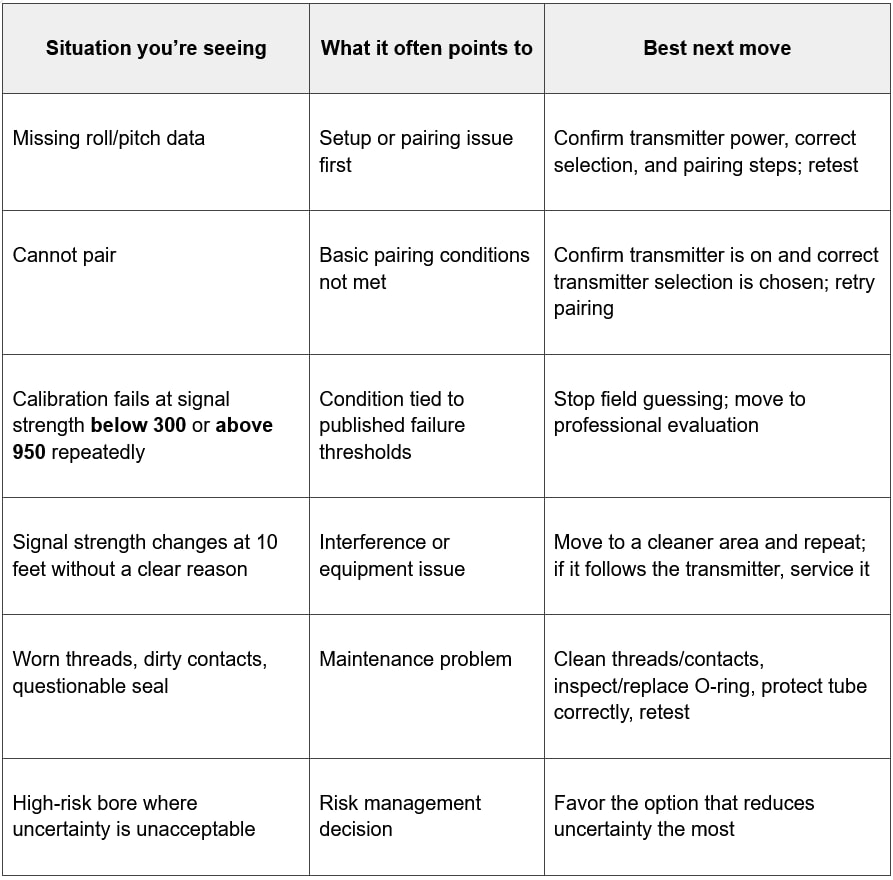
Repair vs. replacement decision table
Use the table as a trigger. When you’re in the “repeatable failure” rows, your best move is to stop improvising and get a diagnostic answer.
If you suspect internal coil/antenna damage: what to do next—and what not to do
Once your checks point to internal trouble, the worst move is to start experimenting inside the housing. Standard warranty terms treat opening up, modification, repair, or attempted repair as warranty-voiding behavior. Even if warranty isn’t your concern, opening the unit without the right process can make diagnosis harder and damage easier.
Instead, do three simple things:
Document the symptom. Write down what you saw: calibration failure condition, missing data, unstable behavior, and whether the problem changed by location or followed the transmitter.
Preserve the state of the tool. Don’t add variables by disassembling anything. Keep protective tape or wraps from blocking key ports (including the IR port), but otherwise leave the unit as-is.
Send it for evaluation. If you need a repair decision you can trust, you need diagnostics. UCG HDD offers mail-in repair service for Falcon F5 locating equipment and FT5p transmitters, and the service listing notes free diagnostics. That’s the right next step when field checks don’t resolve the issue and you need a clear answer.
What not to do is just as important:
Don’t attempt internal repair in the field.
Don’t keep running a transmitter that repeatedly fails against published checks.
Don’t ignore basic care issues like damaged seals or dirty contacts and hope the problem goes away.
Your goal is not to win an argument about the coil. Your goal is to get back to a transmitter you can trust.
Conclusion: fix what you can, then make a clean decision
Most “coil problems” aren’t coil problems. They’re maintenance issues, setup mistakes, or interference. Start there. Clean threads and contacts. Protect the fiberglass tube without blocking the IR port. Inspect and replace a damaged O-ring. Confirm correct transmitter selection and pairing steps. Then retest in a cleaner area.
If the problem persists—especially if you see repeatable calibration failures tied to published signal-strength thresholds, or behavior that follows the transmitter across locations—stop guessing. At that point, repair vs. replacement becomes a risk decision. The fastest way forward is diagnostics.
If you need that diagnostic answer, UCG HDD can evaluate your Falcon F5 transmitter through its mail-in repair service, with free diagnostics noted on the service listing. You’ll spend less time chasing symptoms and more time drilling with confidence.